Wednesday, November 10, 2010

Horn(s) Repaint and Repair

Volvo P1800 (1970) Lucas 9H horns
The horns and their bracket suffered from surface rust, and at the very least needed to be repainted. Interestingly, only the top half of the horns rusted. It appears that the bottom and top of each horn are made from different metals, the top portion being steel. The bottoms must be pot metal  (anyone? )or just have a much stronger plating that remained intact.
In situ, before removal. Note, the rust is only on the top casting of each horn.

Top of the upper horn marked "L"( inside the horn), also stamped 69211B on the top, Lucas 9H on the bottom. The lower horn is marked "H" in the bell and 69205B on the top.

I used sandpaper was used to clean up the flat or gently curving areas; a Dremel tool was able to get into more complex portions. A dark grey primer and flat black paint finished up the job. The bracket definitely had a flat finish, the horns themselves may have been more of satin, oh well.  Before doing all this, it would have been wise to test the horns... You can see what's coming next....
Using a hand drill to drill out the old rivets. Use of the hand drill was easier than getting out an electric drill and should lower the carbon footprint of the project.

As is ends up, one horn was fine, but the other would not sound. To make things more complex, the horns are riveted together. The rivets were relatively soft and where easily drilled out with my wife's help, she held them on the coffee table while I drilled with an eggbeater hand drill. More caution should have been used pushing out the rivets after the tops were drilled out, I bent one of the flanges over the bell. At least I was able to pound it back into shape for the most part...
New gasket and role of gasket material from NAPA.
     The original gaskets appeared to be some kind of felt paper. When wiped with a paper towel saturated in alcohol, a brown residue stained the towel, much like tar. I'm guessing these were a tar impregnated paper? My mechanic thought there were rubberized. One gasket could be reused, the other was replaced with a homemade gasket traced from the bottom half of the horn. The "rubber-fiber" gasket from NAPA was 1/32th of an inch thick (NAPA part number FPG3157 or on Amazon, thicker than the original and I suppose not ideal. Luckily this gasket was for the bell side of the horn and therefor will not effect the solenoid spacing. A RG-59 "F" connector with the outer shell cut off, and the inside tube sharpened made an impromptu hole punch. The inner tube on RG-6 "F" connectors was too large.

Home-brew gasket, home-brew hole punch,  ceramic hammer, and sharpening supplies. The punch (shiny part, center of the photo) is a RG-59 "F" connector with the outer shell cut off revealing the inner sleeve.  The distal edges of the tube were sharpened using diamond files and oil stone to creat a sharp cutting edge.

The solenoid side of the horn.


Once opened, the contacts could be cleaned with doubled over sandpaper. The contacts were slightly misaligned, but I did not try to bend the spring steel back for fear of breaking the whole thing.


Bell side of the horn.
Horn components showing proper orientation and order of assembly.

As per my mechanics suggestion, I used a VERY light coating of Ultra Black gasket RTV to coat both the old gasket and the bell side flange.

Here it the horn put back together. The new paint was removed from the upper surface surrounding the rivet holes to ensure electrical continuity between the top and bottom of the horn. The horn body is the ground for the system and therefor must be electrically continuous from the horn, through the bracket to the car chassis. Stainless steel screws and nuts were used in place of rivets, sorry purists.
Mounting bracket seen from the bottom. Although not listed as separate parts in the manual, the metal washers were not well attached and fell off when I tried to clean them up with a wire brush. Oddly, there was a different kind of paint under them (primer?). 

Monday, October 25, 2010

Charcoal Canister Part 2

A continuation of the last post on rehabilitating the P1800E charcoal canister (click here for first post)
     After priming I decided to try some Bondo Spot and Glazing Putty to even out the top surface and mask my poor smoothing and sanding of the Epoxy used to fill the holes. The putty sanded  easily; it took a few coats to feather the surface up to the highs created by the epoxy. I hope it sticks to the primer! 


Here is the top painted with NAPA high temp flat black paint (it's what I had on hand....) The top although not perfect looks much better.
The bottom obviously still has issues, but hopefully the POR will stop further rusting.  Now all I have to do is find a filter to fit in the bottom.
All finished with the bracket at the base, when installed, the bracket sits closer to the middle of the cylinder. Again, not perfect, but much better! It should work once I find/make a filter for the bottom, and oh, yea, get the engine out of the car and fixed...put back in.... etc. etc...

Sunday, October 17, 2010

Front Turn Signal Lights

Unpolished, covering Nixon's face
Unpolished


Polished, but note two symmetrical reflections in the center, closeup below.
Clearly, this is an octopus, note the eye. Also, note, there were no octopuses present.... ghost?  Call captain Nemo!

Saturday, October 16, 2010

Heater air intake grille

This is the oval grille just front of the windshield on the hood that allows fresh air to enter the heater box. I though it was just aluminum and would be easy to just polish up. It is made of aluminum, but appears to be anodized. The coating looks like chrome, but based what I've read, aluminum is typically anodized for car trim and not chromed? When I think of anodized aluminum I picture the black coating on Calphalon pans.... I tried to clean it up with metal polish which did improved the surface, but its not great.... I guess I could sand off the anodizing and buff it up, but that might be an overkill at this time, furthermore it would need some kind of cleat coating to keep it looking good.... the trim looks better and a quick coat of black paint on the grate neatened it up.


Before polishing and painting.
After fresh paint and polishing. It's hard to see a big difference between the two, its not perfect, but better.

Before
After
Here is bracket that holds the grille to the body. There are three of these, I was able rotate them out from under the lips on the underside of the grille to remove the great for painting.

Thursday, October 14, 2010

Charcoal Canister (Evaporative control system)

The charcoal canister is part of the evaporative control system. According to Wikipedia, all cars sold in the US starting in 1971 (1970 in CA) needed to be equipped with a fuel evaporative control system. The idea is to prevent fuel evaporating from the gas tank entering the atmosphere; traditionally, expanding fuel vapor was released to the atmosphere. To prevent this the gas tank filler cap is sealed, thus forcing evaporative gases through a vent hose that lead to a canister containing activated charcoal. As the gas passes through the canister the charcoal sequesters the hydrocarbons and the "clean" air is then vented. When the car is running, air is sucked back through the charcoal and into the engine, burning off the gas vapor.
     This Volvo canister (for a P1800) is open on the bottom to vent the filtered gas and to allow fresh air to enter the canister and passing back through the charcoal when the engine. From what I can tell (quick Google search) gasoline vapor is heavier than air, and therefor I don't understand why fuel vapor would not leak out the bottom of the canister? If the charcoal does hold on to the vapor well enough to prevent it leaking out the bottom, what makes the sequestered vapor "release" when the engine is pulling air back through the charcoal? Anyone? Inquiring minds want to know....
     Regardless, the canister must have worked, or at least was better than just venting unfiltered gas - so the charcoal canister will get a makeover.

Here is the charcoal canister with the hold down bracket removed; the less rusty band shows where the hold down bracket attached. The canister assembly sits between the front grille and radiator (I just learned that grills are for cooking and grilles are for cars).
      There were a bunch of holes rusted through the canister top, which, if the EVAP system is to work, clearly need to be filled. Given that the bottom also had extensive rust, I should probably have looked for a new or used replacement in better condition. Word on the interwebs is that the charcoal itself does not go bad, so I assume it does not need replacement (if it did, I wonder if aquarium filter charcoal would work?). I also hear that you don't really need the canister for the car to run correctly; but I do want to be somewhat eco friendly and it may also cut down on the gasoline smell in the garage.  The canister itself is obscured by the radiator from the perspective of the engine bay, and by the front grille from the outside. Therefore we don't need perfection, just function. So I tried to plug the leaks, stop some of the rust, and make it look good enough that I will not be embarrassed to show pictures on this blog (all two or three of you - feel special).
   A wire brush and sandpaper were used to remove rust scale, and a small amount of what I presume was a rubbery underbody coating. Before filling the holes with JB Weld, the top was coated with POR-15 "silver"paint, allowed to dry, and then scuffed up to provide key for the JB Weld adhere (not sure if that was necessary).

The base of the canister. Note bits of the filter remaining on the left edge under the rusted steel lip. (Click for larger image)
Close up of the vents on the bottom; in the larger wholes you can see some kind of mesh that must hold the charcoal in place.

This is the best photo of the holes. The top has been coated in POR-15 Silver. The largest hole is South-East of the outlet on the top.


JB Weld Stik. This is a two part epoxy that is kneaded together to catalyze. In cross section it looks like a corn dog (click for the wiki photo of a corn dog cross section).


The hardened JB Weld. I got it as flat as I could, but it's still mounded up.
After the JB hardened, I used a Dremel tool to grind off the high spots and somewhat feather the edges of the epoxy. More grinding and sanding could have produced a flatter surface, but that did not seem necessary given the 'hidden' location of the canister.
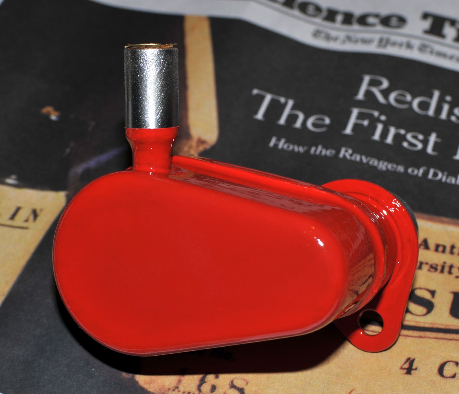
     After the grinding of the JB, the whole top and sides of the canister got two coats of POR-15 and a few light coats of primer.

Coated in primer, waiting for the final coat and maybe light sanding.
Now its time to start on the base.  EDIT. Blog magic, click here for part two.


Thursday, October 7, 2010

Temperature Sensor

Bosch Coolant Temperature Sensor (0 280 130 014)
Before Cleaning (obviously) Bosch 0280130014

After cleaning and polishing

You can even get it on Amazon, who knew...


Results from testing the sensor in a pot of water on the kitchen stove. Measurements started out in ice water and continued until the water boiled. Measurements from my sensor are the blue X's. The other data is from J. Tang's blog and includes his original and new sensors (much nicer than mine, he even shows the test setup, I was too lazy to clean the stove for a photo shoot, plus, you would laugh at how the multimeter and thermometer were set up.....) This data was collected with a food thermometer and a Fluke Multimeter, all data was collected in good faith and is believed to be accurate. This data comes with no warranty, expressed, or implied, and should not be used to diagnose any part of a motor (or any other means of propulsion) vehicle that might carry a person(s), pets, valuable artwork, or Tribbles. This data is for entertainment purposes only! Although the entertainment value in not warrantied. In fact, just don't look at the data.

Graph of the data from my sensor with the upper and lower limits interpolated from the Volvo Shop Manual, see below. It would seem that my sensor falls within the correct range and would seem to be OK. Yay! 


From the Volvo Service Manual or "Green Book"
My raw data..... Left column resistance in Ohms, right column is temperature in F.
4280 43
4310 42.8
4500 41.9
4590 37.4
4460 37.6
4440 38.3
4150 48
3700 52
3200 59
2990 61
2800 62
2808 61.3
2585 69
2330 73
2180 77
2028 80
1948 83
1820 85.5
1700 88.7
1600 90.7
1500 94.6
1431 95.2
1431 95
1432 95.2
1350 101.5
1200 107.1
1100 111.4
1000 116.6
900 122
800 128.3
700 135.7
600 144.5
500 155.3
400 167
350 175.6
300 185
270 192.2
250 196.3
240 200
220 204.3
210 207.5
203 207
200 208
197.4 208.2
199.5 209


Tuesday, October 5, 2010

Oil Trap/Crankcase Breather


These photos were taken after the 2nd coat of POR Engine enamel. Toward the left edge of the oil trap you can see where the paint sagged, being thicker, the sag has a fully developed color, which of course highlights the regions that do not. Switching to a better brush allowed me to get more consistent, but thinner coats of paint.  The first coat on this parts was made with a cheap disposable brush that resulted in thicker but uneven coats prone to drips and sags. No more cheap brushes, except for the POR-15 (requires lacquer thinner vs. just paint thinner).  I guess I should give this a 3rd coat, but again, I'm not sure how visible this part will be, and from two feet away without strong lights it looks great; it wants to avoid the limelight I guess. I'm going to put this in the done pile, maybe when the paint is out again for the engine I will give it a third coat....